MASS FLOW
Based on the mass flow rate the flow resistance of ports or other air-guiding components can be evaluated.

The combustion process is strongly influenced by intake flow quantity and quality. Therefore these factors are of considerable importance in engine development and optimization aiming on increased efficiency and minimized pollutant emission. Flow Measurements on Momentum FTBs offer a way to determine characteristics, summarizing the fluidic properties of intake and outlet ports as well as peripheral air guiding components. Measurements on PIV FTBs provide detailed insight into the flow entering the cylinder by means of visualized velocity fields (suitable for comparison with CFD). Also flow characteristics can be derived from the velocity fields to simplify comparison between samples.

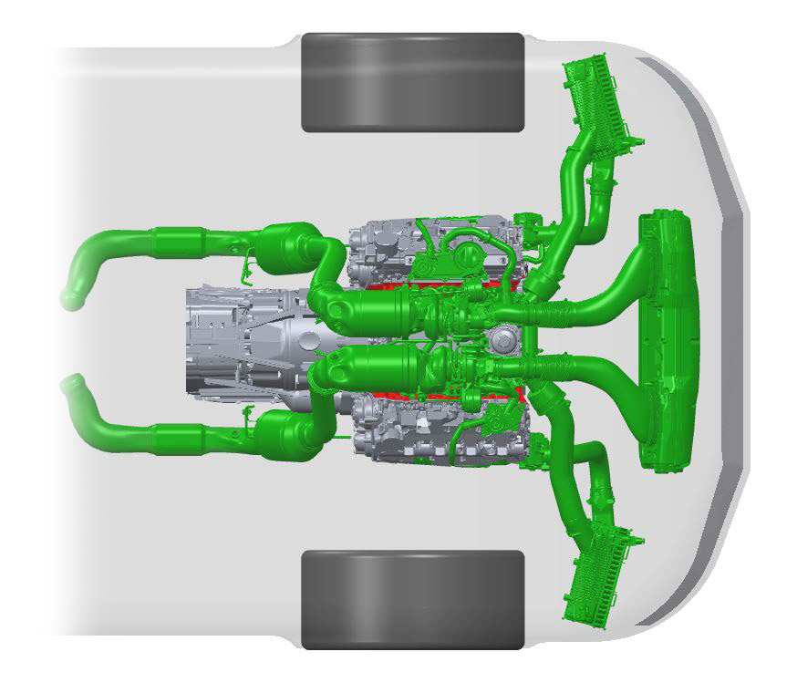
Exhaust system Testing
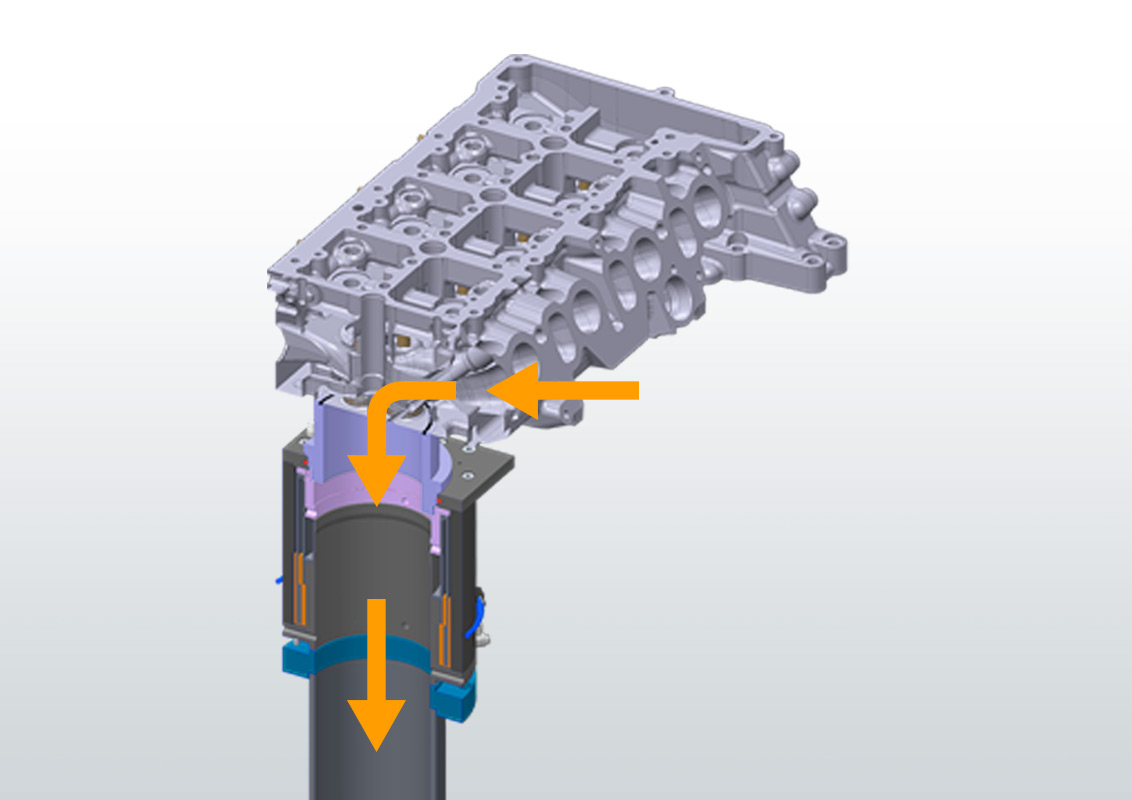
Multi Cylinder Head Testing

Catalyst and Particular Filter Testing
Air Filter and Air Box Testing
Intercooler Testing
Based on the mass flow rate the flow resistance of ports or other air-guiding components can be evaluated.
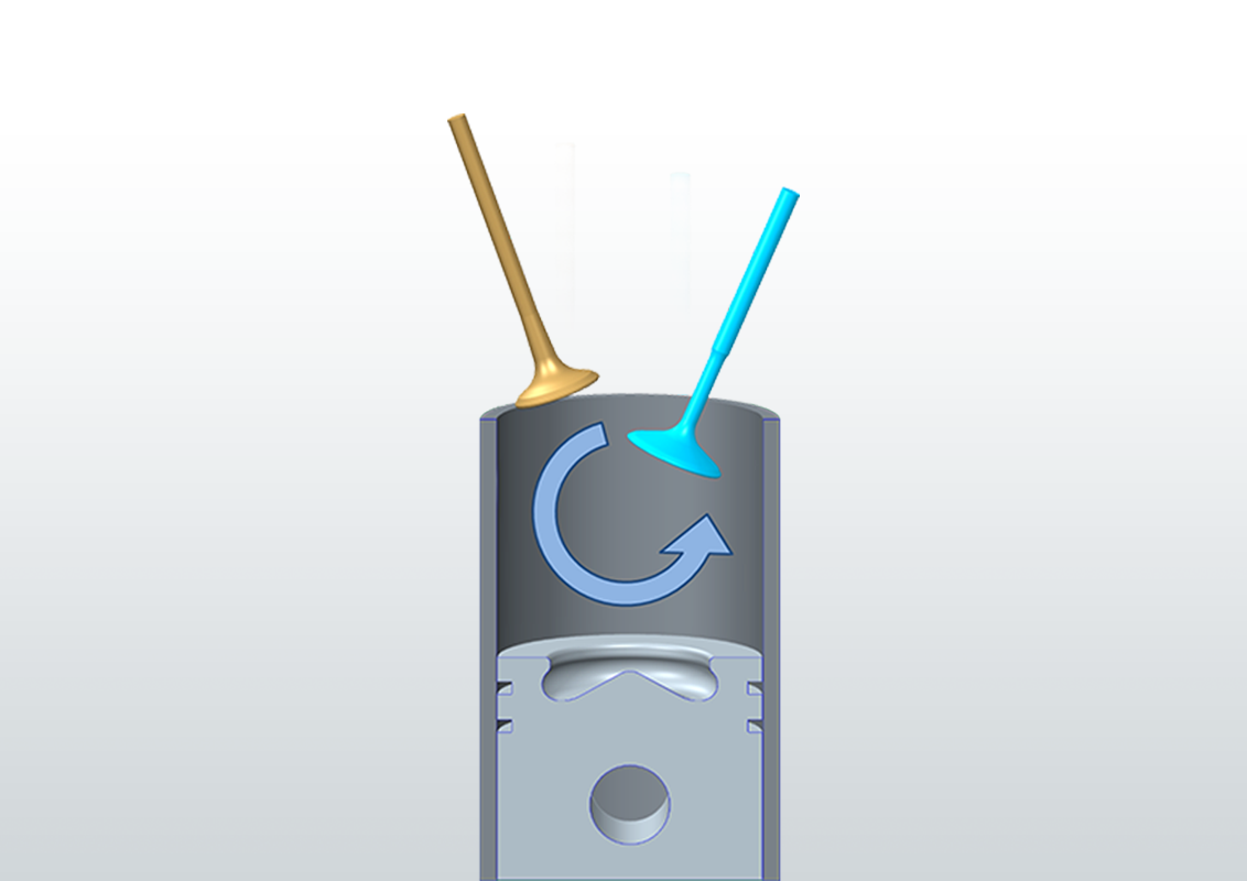
The rotational movement about the cylinder axis is referred to as swirl. Swirl is typically of relevance for diesel engines.
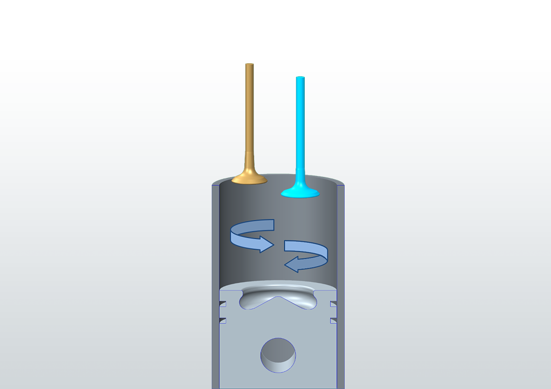
The rotary motion about an axis perpendicular to the cylinder axis is referred to as tumble. Tumble is typically of relevance for gasoline engines.

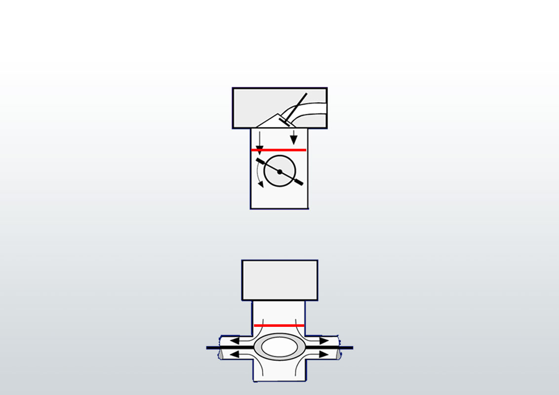
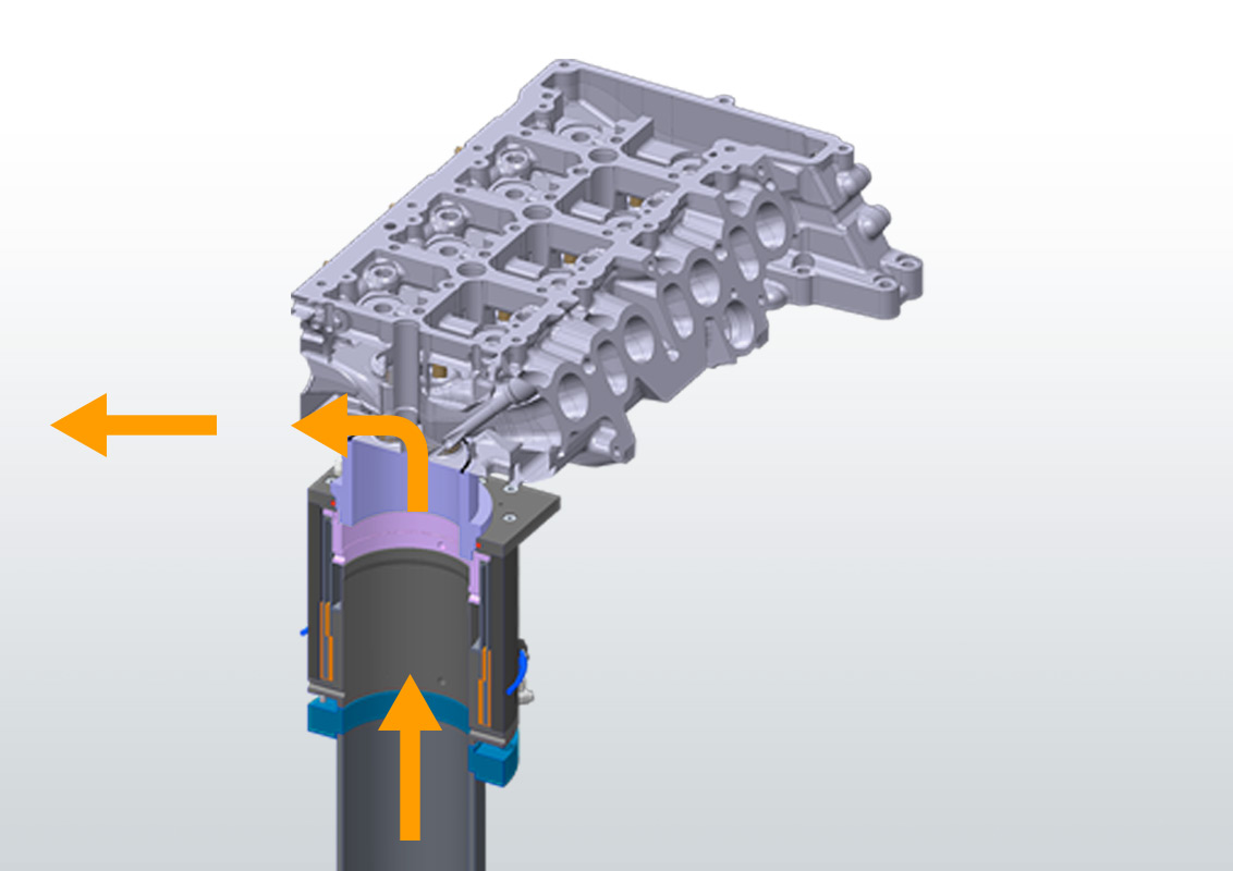
A one-dimensional Flow Straightener (sometimes referred to as „Honeycomb”, because of the body structure) orients all velocity components of an arbitrary flow in one direction parallel to the cylinder axis. This means, all deviating momentum components are blocked by the flow straightener which causes reaction forces/torques in the bearing. Therefore the torque measured at the bearing represents the integral of the momenta in tangential direction over the Flow Straightener surface, referred to as Swirl. Besides the fact that there is no rotation (and therefore no undefined friction) of the device, the main advantage of this method of Swirl measurement is, that the quantity of interest is captured over the whole cross section at once and the result is valid without any assumptions concerning the flow (in contrast to the necessary “rigid disc”-assumption for winged wheels).

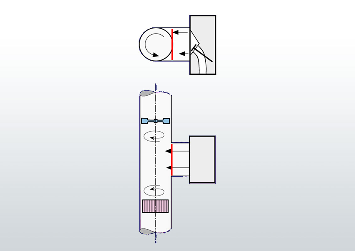
With the three-dimensional Flow Straightener the measurement principle described above is extended to all three dimensions of torque, delivering three components of swirl (Swirl around the cylinder axis and the two perpendicular components combined to Tumble) with one measurement. To achieve this, the cross section is transformed into a spheric shape and allows the flow to pass only in radial direction. The advantage of this method over all kinds of winged wheels (placed directly in the cylinder or – even worse – in a subsequent T-piece) are obvious in the measurement results, that show a good correlation e.g. with PIV results.
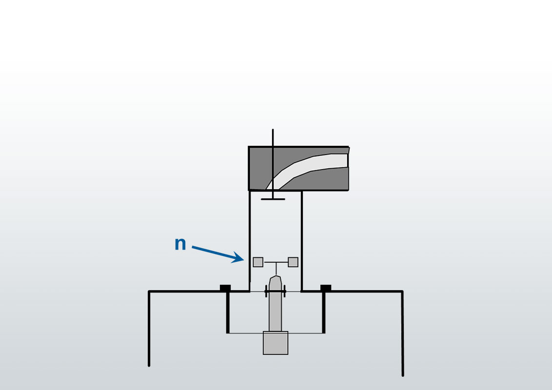
These kinds of swirl measurement devices are based on the idea to place a functionally shaped solid body pivot mounted in the flow, measure the rotational speed and draw a conclusion concerning the quantity of interest (swirl or tumble). This approach could only be successful if the rotation axis of such devices were congruent with the swirl axis, the swirl were homogenous (“rigid disc rotation”), the device could cover the whole cross section and the retardation by friction could be excluded or quantified – none of which is realistic. The additional assumption that flow components are conserved over long distances and even through changes of direction imposed by the piping – which would be essential for correct measurements using a T-piece – is at least rather optimistic. In modern equipment such devices should only be used to assure compatibility with existing databases.
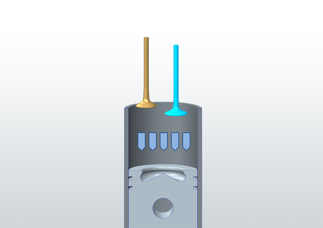
Mass flow
Swirl/Tumble
Mass flow
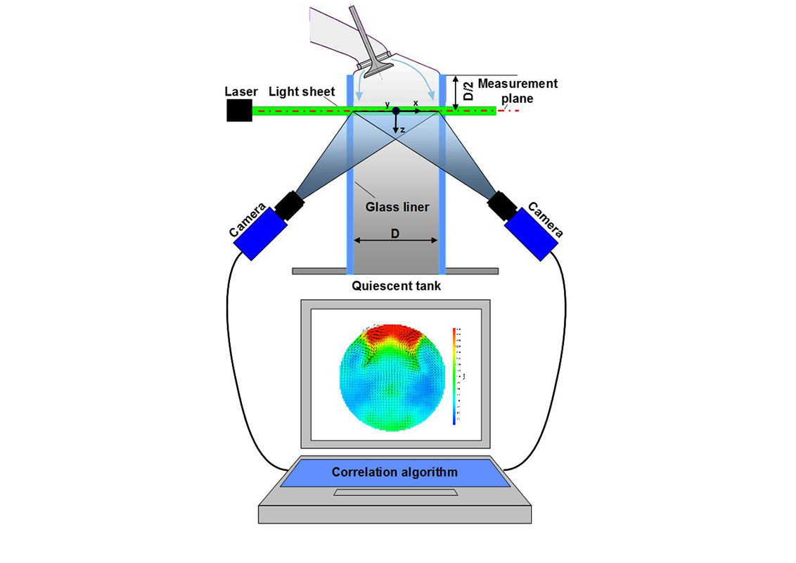
In PIV-measurements (particle image velocimetry) microscopic particles are illuminated by laser light sheet during two closely timed pulses and simultaneously recorded photographically. Using two cameras the spatial components of particle motion are obtained, from which the three-dimensional velocity field in the measuring plane is determined. The velocity fields can be visualized and are well suitable for the validation of computational fluid dynamics results.
Quantity of a fluid that passes a cross section during a given time
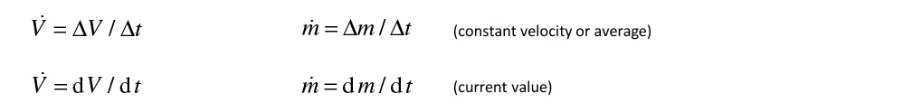
with du (length increment at cross section A during dt):

→ for constant velocity c:

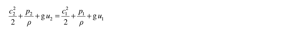
If differences in altitude can be neglected, the energy balance can be written as:

using the terms
pst = p (static pressure)
pdvn = r c2 / 2 (dynamic pressure)
ptot (total pressure)

in resting fluid (c = 0)

(index 1: tank conditions; index 2: ambient conditions)
the second square root in the expression obtained for the mass flow is the function y* describing the leak flow
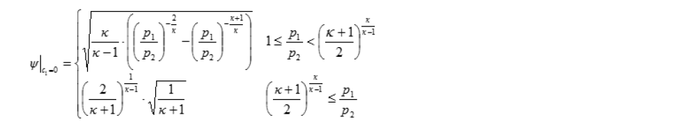
Aeff is a characteristic value with the physical unit of an area and serves for the comparison of flows through different air ducts (ports) at a given pressure drop
Incompressible Flow (assumption)

Compressible Flow

Tippelmann Swirl and Tumble Coefficient are derived from the torque measured on the flow straighteners.
Tippelmann Swirl Coefficient

Tippelmann Tumble Coefficient and Angle

Paddle Wheel measurement was the first attempt to determine a swirl proportional quantity to compare different ports. It is a
but
Besides, this Paddle Wheel measurement obtains valid results only if:
Advantages of Momentum Principle (Torque based using Flow Straighteners)

Real flow field with inhomogeneous velocity distribution ≠ “rigid disc”

Area covered by paddle wheel
(rotational speed fluctuation is not taken into account)

Area which is detected by flow straightener –
complete detection (100 %) of area of interest

Real flow field with inhomogeneous velocity distribution ≠ “rigid disc”

Area covered by rotating ring
(rotational speed fluctuation is not taken into account)

Area which is detected by flow straightener –
complete detection (100 %) of area of interest


Tippelmann Swirl and Tumble Coefficients derived from velocity fields generally show satisfying similarity to the respective values determined from torque measurements on flow straighteners. This illustrates the reliability of the Tippelmann method and shows that the two basic approaches can complement each other depending on the field of application.

